As an Electrical Contractor, I stopped playing with EE puzzles ages ago.
As for the matter at hand, this is nothing but algebra with complex numbers.
It looks like it's been lifted from a Schaum's outline book.
When I was taking college Physics, the graduate students would 'mine' Shaum's all of the time. They were so lazy they wouldn't even change the variables.
This equation is either right in there or something like it.
BTW, the notation used might introduce confusion.
A bar over a variable figures to indicate that the value is a Tensor. (Vector)
http://en.wikipedia.org/wiki/Tensor{ All vectors are tensors, too. }
http://en.wikipedia.org/wiki/Electromagnetic_tensor( One need not go all of the way deep into QED and the rest of wave physics. )
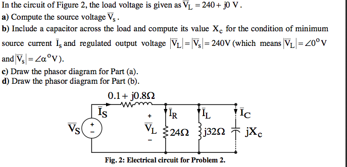
In other settings that same bar symbol indicates DC vs AC current. So, your diagram seems odd.
In your equivalent circuit -- no such beast could actually be constructed -- ALL of the load has to pass through the resistor. The first resistor is NOT deemed to be part of the load.
In this idealized circuit the inductor and capacitor have ZERO resistance. They just bounce the current around.
I dislike the use of the L subscript for both Load and inductance.
BTW, it's strongly implied that the inductance and capacitance HAVE to balance -- perfectly -- to obtain minimum source current.
The algebra follows rather directly, doesn't it?
Best of luck.


