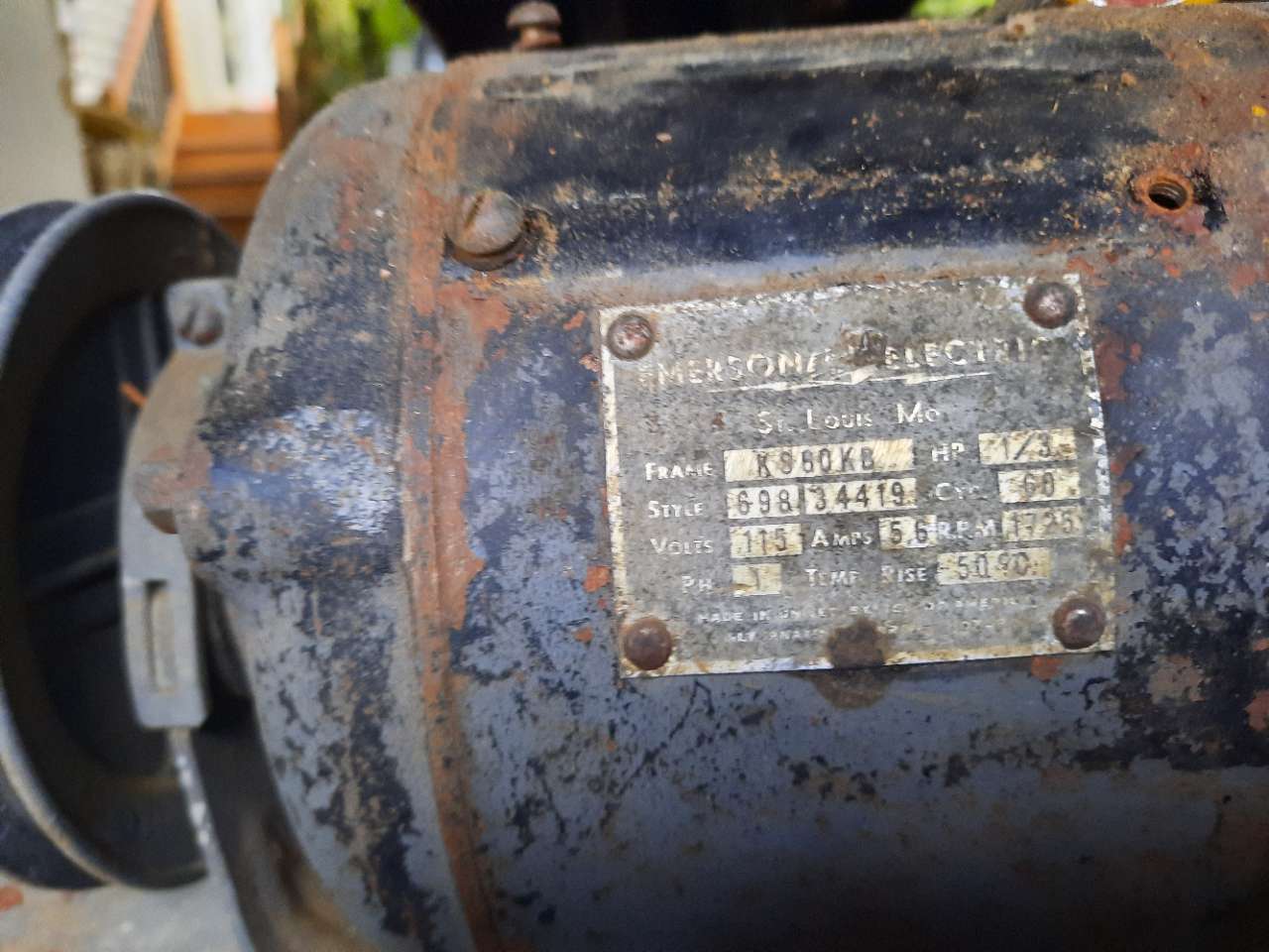
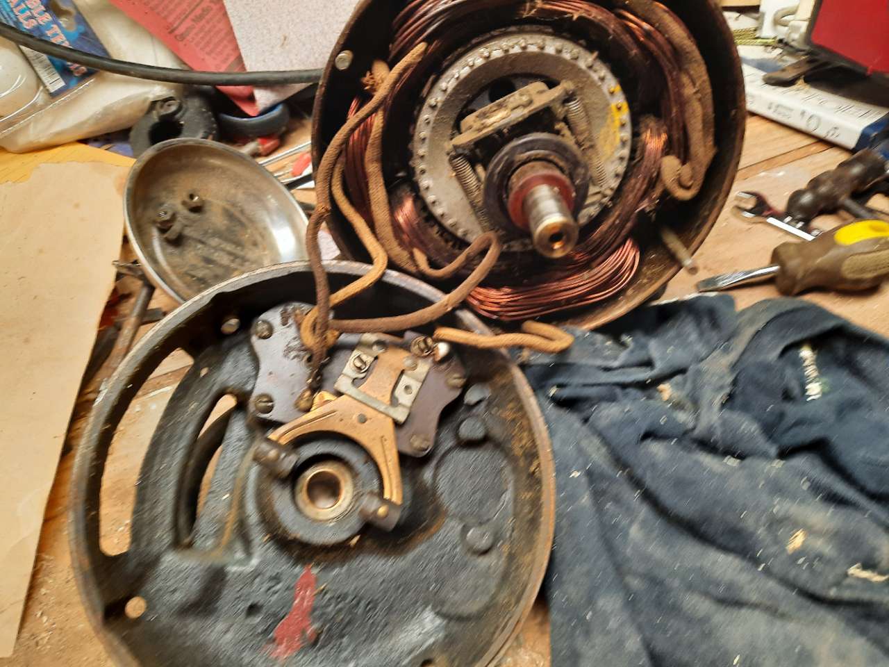
First let me say I am not a professional. But I need the help of a professional. I have an old Emerson Motor picture attached belonging to a vintage craftsman Jointer. My quandary is what wire of the cord goes to what Terminal? there are four terminals. I opened up the motor and tested every thing for continuity and here is what I have found. Terminals #1 and #3 are connected to the run winding. Neither of them test for continuity with either of the other wires? The wire from #2 goes to the start winding, capacitor and ends at centrifugal switch ( bar underneath switch) Term. #4 connects directly to the base part of the switch. All the diagrams I have looked at show the run winding circuit being in parallel with the start winding circuit. But if it is shouldn't I find continuity with the other circuit this is where I am confused. Crude diagram attached. I do understand the basics of how this motor operates but I am missing some thing here. Any knowledge any one could give me would be welcome. Also mainly which terminals would the hot and neutral be connected to. If there's any other testing I can do? Thanks Much
Description: Motor

Description: Crude schematic??

Description: motor open

If you test for continuity through a capacitor that won't work with an Ohmmeter.
To check the other (start) winding for continuity you need to bridge across the capacitor and see what readings you get.
Normally a run winding has a thicker gauge wire, and will have a lower ohm reading. (e.g. 12 Ohms)
A start winding has a thinner gauge of wire, and will have a higher ohm reading (e.g. 17 Ohms)
Try to do an insulation check first, and see if there is no winding short to earth (motor frame).
Check the centrifugal switch if it works. (should be closed at standstill).
That wire insulation looks brittle and may need some additional sleeving.
To do a simple testrun and see if the motor works. Connect 1 and 3 to a 110 volts supply, the earth to the exposed motor frame (safety), the motor should hum, it may sometimes even start without a start winding energized.
Switch power off !
Give the pulley a push with a stick or wrap a string around the pulley, before energizing. Pull the string, so the pulley and armature rotate, then energize the motor and see if it works.
Now test the motor with start winding.
If the start winding and capacitor is ok. connect 1 and 2 together on Active, or Phase and 3 and 4 together on the Neutral.
The motor should start and run, centrifugal switch should switch start winding off.
To change rotation of the motor, connect 1 and 4 to Active and 2 and 3 to Neutral.
That flips over the start field and the motor will run the other way
Hope it helps.


