ECN Forum
Posted By: akmaster Temp Power Grounding - 05/09/13 04:56 PM
I have a lot of temp power transformers setup on a job...they are fed by a 480V then steps down to 120/208...

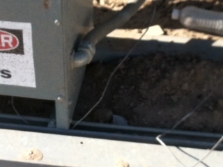
The XO is bonded to the case then a #6 should be connected to a ground rod or grid correct? Even if temporary correct?

Please see photo..if possible point me to the NEC article.

Thank you again.

Greg


Description: Transformer with #6 not connected to anything...NEC article? This should be grounded to a ground rod even if temporary.
Attached picture unngrounded_xfmr.jpg
Posted By: HotLine1 Re: Temp Power Grounding - 05/09/13 07:24 PM
This is from the '08 Handbook.

250.30 Grounding Separately Derived Alternating-Current Systems.
(A) Grounded Systems. A separately derived ac system that is grounded shall comply with 250.30(A)(1) through (A)(8). Except as otherwise permitted in this article, a grounded conductor shall not be connected to normally non–current-carrying metal parts of equipment, to equipment grounding conductors, or be reconnected to ground on the load side of the point of grounding of a separately derived system.
FPN: See 250.32 for connections at separate buildings or structures, and 250.142 for use of the grounded circuit conductor for grounding equipment.
Exception: Impedance grounded neutral system grounding connections shall be made as specified in 250.36 or 250.186.

Posted By: akmaster Re: Temp Power Grounding - 05/09/13 08:17 PM
Thanks for the reply HotLine1...so are you saying that the XO bonding to case and then to ground is not allowed?

Sorry for the confusion..

Thanks

Greg
Posted By: akmaster Re: Temp Power Grounding - 05/09/13 08:25 PM
Is this the exception you are talking about ?

Exception: A grounding electrode conductor is not required for a system that supplies a Class 1 circuit from a transformer rated not more than 1000 volt-amperes. However, the system grounded conductor must be bonded to the transformer frame or enclosure in accordance with 250.30(A)(1).

..
Posted By: HotLine1 Re: Temp Power Grounding - 05/10/13 02:32 AM
akmaster:
Let me say this in easy form. The transformer XO (Neutral or grounded conductor) is one point that the GEC can be terminated at. This is also the point that the bond for the transformer enclosure is bonded to, usually with a factory ground strap. A compliant field installed bond is also acceptable.

The GEC from the transformer can be terminated at the building steel, metalic water piping, ground ring, rod(s), etc.

Article 250 can be one of the tougher to get a grip on.

Posted By: akmaster Re: Temp Power Grounding - 05/10/13 02:41 PM
Thanks Hotline...so if the transformer has a factory installed BONDING Strap attached to the case from the same point that the xo IS BONDED TO THE CASE then NO ground rod or other GEC is required?

You are correct article 250 is tricky and one of the most important sections in my opinion.

Sorry for being so dense!

Thanks

Greg
Posted By: HotLine1 Re: Temp Power Grounding - 05/10/13 03:21 PM
No, the bond strap or field installed compliant conductor ONLY bonds the enclosure!

The neutral (XO) must have a compliant GEC. (Rod(s); steel;Ufer;etc.)
Posted By: akmaster Re: Temp Power Grounding - 05/10/13 03:28 PM
OK! Great thank you very much for the help!

best regards,

Greg
Posted By: gfretwell Re: Temp Power Grounding - 05/10/13 04:50 PM
That article is confusing. Your first assumption was right. You hook your GEC to the XO and that is also where the can usually gets bonded. All of that other language is just saying you have a ground and neutral radiating from that point that never meet again.
Posted By: HotLine1 Re: Temp Power Grounding - 05/10/13 08:24 PM
Greg:
You should submit the above words to NFPA.
Posted By: Scott35 Re: Temp Power Grounding - 05/11/13 09:31 AM
AKMASTER:

Per HotLine1's post:

Quote

No, the bond strap or field installed compliant conductor ONLY bonds the enclosure!

The neutral (XO) must have a compliant GEC. (Rod(s); steel;Ufer;etc.)


The Attached Drawings may be of assistance:

[Linked Image]

Fig. 1: Front View of Transformer - Details of Lead Terminations.
---------------------------------------------------------------------------------

[Linked Image]

Fig. 2: Top View of same Transformer.
a.: GEC runs out the back of the Transformer;
b.: Primary Feeders enter on the Right-Side of Transformer;
c.: Secondary Feeders exit on the Left-Side of Transformer;
d.: 3-Terminal Lug with Green Bolt (connected to XO Lug via System Bonding Jumper) is Physically Bonded to the Transformer Enclosure.
---------------------------------------------------------------------------------

[Linked Image]

Fig. 3: Transformer Winding Connections Schematic, with OCPDs and SDS Panelboard.
.......................................

Figure #3 Notes:

1.: On the Secondary side's Connections, Terminal "XO would be physically located at the "Dot" above the Green Grounding Bus.

2.: The "Ground Symbols" on the Primary and Secondary sides, are Physical Connections to the Transformer's Enclosure. These Terminations may be either a Factory-Installed Jumper, or a Field-Installed Lug.

------------------------------------------------------------
------------------------------------------------------------

These Drawings, along with many others, may be found at the Technical Reference Section of ECN.

--Scott (EE)
Posted By: HotLine1 Re: Temp Power Grounding - 05/11/13 03:10 PM
Scott:

As always, Thank You for the added info.
Posted By: Scott35 Re: Temp Power Grounding - 05/16/13 03:34 AM
Any time John!!!

--Scott (EE)
Posted By: akmaster Re: Temp Power Grounding - 05/16/13 03:38 PM
Thank you very much for your time and feedback!

regards

Greg
© ECN Electrical Forums