ECN Forum
Posted By: Redmarshall Please help me wire this old Teco motor! - 01/15/15 04:35 AM
I have an old Eaton's of Canada TECO electric motor that I am trying to wire properly but I cant find any diagrams on the web for this model.

It is a 110/220 volt, 9.4/4.7 amp, 60 hz, 3/4 hp, single phase, capacitor start motor.

There are only 5 wires:

Black
Red
White
Yellow
Blue

I just replaced the cap.

The motor seems to run fine when I connect The black wire to the hot and the white to the neutral but what are the other 3 wires for?
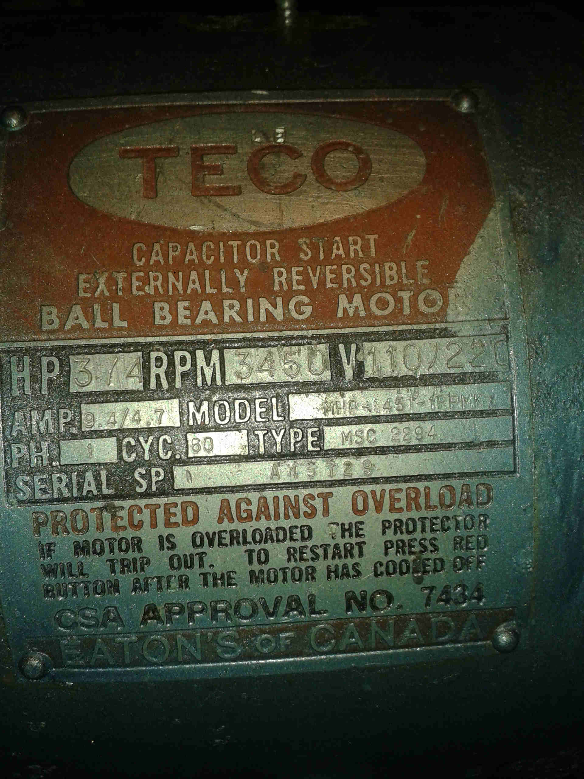
Attached picture 20150114_175911.jpg
Are you sure there is not an orange wire tucked in there somewhere?

Usually the red and black are the start windings and you have two run windings (for 120 or 240v). They get wired in series for 240. If you reverse the relationship between the start and run windings you reverse the motor.

[Linked Image from gfretwell.com]

[Linked Image from gfretwell.com]
That is a flash from the past The Eatons brand Teco smile
Posted By: Scott35 Re: Please help me wire this old Teco motor! - 01/19/15 08:05 AM
Adding to Greg's Post...

For a Dual-Voltage Capacitor Start Motor, with Two Main (Run) Windings and One Auxiliary (Start) Winding, there Should be a total of (6) Wires:
  1. Terminal #1 to Main Winding #1: Color = Blue,
  2. Terminal #2 to Main Winding #1: Color = White,
  3. Terminal #3 to Main Winding #2: Color = Orange,
  4. Terminal #4 to Main Winding #2: Color = Yellow,
  5. Terminal #5 to Capacitor, via Start Switch: Color = Black,
  6. Terminal #8 to Auxiliary Winding: Color = Red.


For Low Voltage Counter-Clockwise Rotation (Forward), the following Leads are connected together - with the Line Input Terminated to:

Line #1: Leads 1, 3 and 8
Line #2: Leads 2, 4 and 5

For Low Voltage Clockwise Rotation (Reverse), the following Leads are connected together - with the Line Input Terminated to:

Line #1: Leads 1, 3 and 5
Line #2: Leads 2, 4 and 8


Quote


I just replaced the cap.


Did you notice the Leads connected to the Capacitor?
If possible, disconnect the Capacitor, then trace out the Leads on both sides of the Capacitor, in order to identify the Auxiliary Circuitry (Aux. Winding, Start Switch and Capacitor Leads) from the Main Windings' Circuitry and Leads.

Quote


The motor seems to run fine when I connect The black wire to the hot and the white to the neutral but what are the other 3 wires for?


Are these Connections being made at the Reversing Switch Termination Box, or elsewhere?
Also, are you connecting the Motor to 120VAC?

From the descriptions, I would say the Motor is running on only One Main Winding, in the Reverse Direction (Clockwise Rotation, as viewed from the Motor's Shaft).

Will post more after OP's Feedback.

--Scott (EE)
© ECN Electrical Forums